← A complex number as a vector: I and Q
Why a receiver must tell the two directions apart
Let a receiver be tuned to 7.100 MHz. Two signals are 1 kHz below and 1 kHz above the tuning frequency. The receiver must tell them apart to select the necessary signal.
For this, it is easy to describe frequencies relative to the tuning frequency:
| Input frequency | Difference from the tuning frequency |
|---|---|
| 7.099 MHz | −1 kHz |
| 7.100 MHz | 0 Hz |
| 7.101 MHz | +1 kHz |
In the complex representation, we can show this difference as rotation: a positive difference turns counterclockwise, a negative difference turns clockwise. In this lesson, we examine how to write such a signal. We discuss how to shift the radio frequency to zero in the next lesson.
Frequency as a change of angle
For a complex tone with amplitude 1 and initial phase 0:
Between adjacent samples, the angle changes by
When , the angle increases: the vector turns counterclockwise. When , the angle decreases: the vector turns clockwise. The sign of the frequency shows the direction, and the absolute value shows the number of turns per second.
For a positive number , we write both cases:
They are conjugates: . Here this is true because the amplitudes are the same and both initial phases are zero.
I is the same: 0.707 · Q is opposite: +0.707 and −0.707
In the diagram, kHz, kS/s. The left vector makes a step, the right vector makes a step. Change the sample number one step at a time and look at the coordinates.
| Angle of | Angle of | |||
|---|---|---|---|---|
| 0 | 0° | 0° | ||
| 1 | 45° | −45° | ||
| 2 | 90° | −90° | ||
| 3 | 135° | −135° |
Which coordinate tells these signals apart
Compare the columns: the real parts are the same, and the imaginary parts are opposite. This is a known property of cosine and sine:
If you keep only , the two rotations shown give the same arrays. The coordinate lets you tell them apart. We will need exactly this for signals on the two sides of the tuning frequency.
Rotation relative to the tuning frequency
Think of a vector at 7.101 MHz and an observer who turns in the same direction at 7.100 MHz. Relative to the observer, the vector makes only 1000 additional turns per second: kHz.
A vector at 7.099 MHz, on the other hand, falls behind by 1000 turns per second: the frequency offset is kHz. When the frequencies are equal, the relative angle stays constant. It is not necessarily zero: it depends on the initial phases of the signal and of the reference rotation.
This is a geometric model of a frequency shift (downconversion). In practice, multiplication of complex signals does it. The frequency of the reference oscillator is the LO (local oscillator) frequency. For now, the numbers in MHz describe the radio frequencies of the device; we do not try to sample them directly at kS/s. This sample rate is sufficient only for our slow rotations near zero.
Complex samples also have aliasing
At kS/s, a kHz rotation turns per sample by
This rotation goes to the same point as . Thus a kHz complex tone gives the same samples as a kHz tone, if the amplitude and initial phase are the same.
At this , the pair tells kHz and kHz apart, but it cannot tell apart frequencies that differ by an integer multiple of . If you keep only , you also lose the difference between these two directions.
Lab: we compare two rotations
The script shows the vectors, their real parts and the accumulated phase:
uv run labs/02/02-positive-negative-frequency.py --show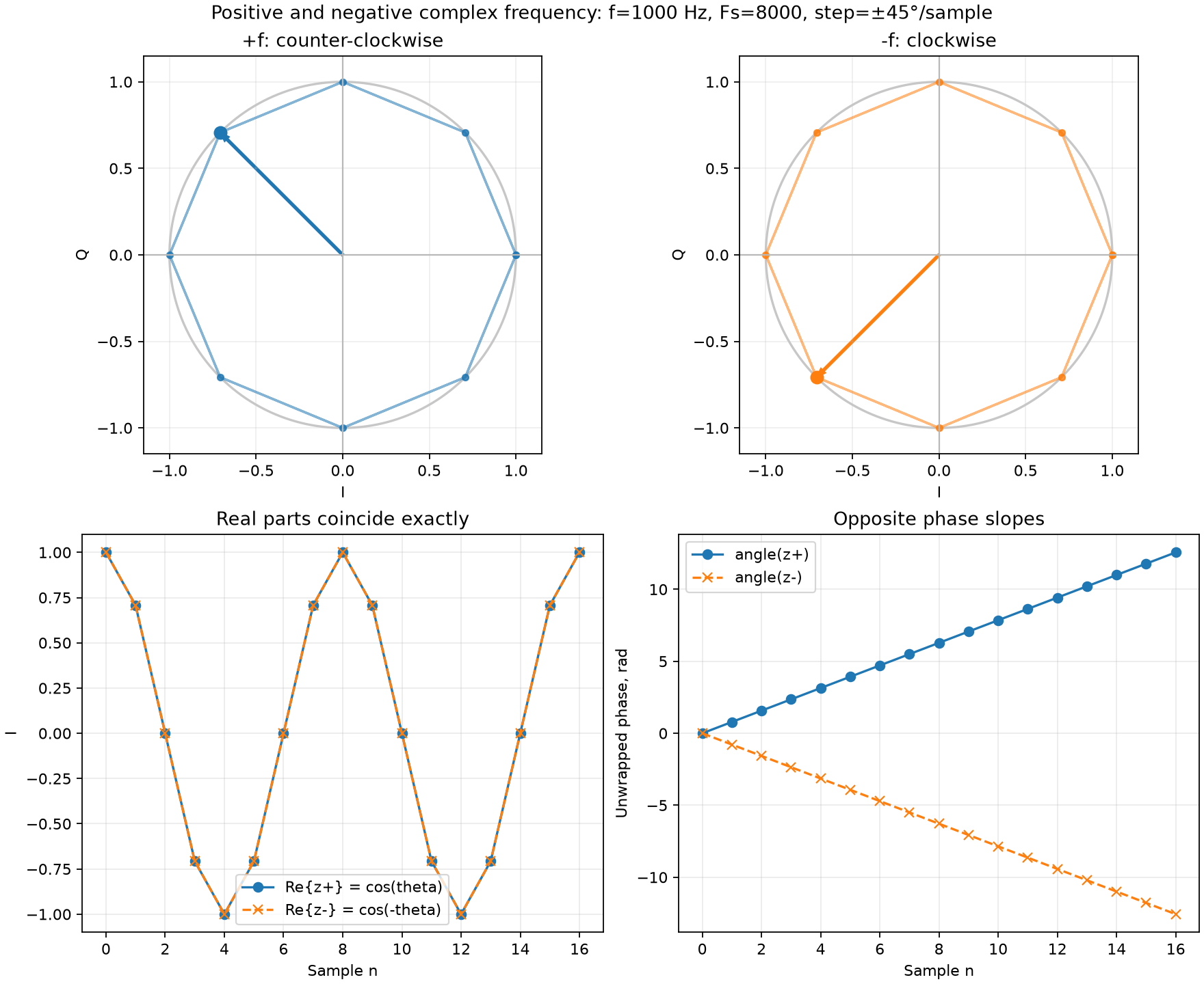
For the positive frequency, the accumulated phase increases. For the negative frequency, it decreases. The real parts are the same. Try a step instead of :
uv run labs/02/02-positive-negative-frequency.py --f 2000 --show --output-dir /tmp/dsp-negative-frequencyThe script prints the maximum differences between the real parts, and between and the conjugate of . Both values must be near zero, within the calculation error.
Self-check
The tuning frequency is 7.100 MHz. The signal is already shifted to baseband: each frequency is an offset from the tuning frequency.
For a signal at 7.102 MHz, find the frequency difference “signal minus tuning”. In which direction does its vector turn in the new coordinate system?
The frequency offset is kHz. When , the angle increases: the vector turns counterclockwise and makes turns per second.
The same question for a signal at 7.098 MHz.
kHz. The absolute value is the same as for the previous signal, turns per second, but the direction is opposite: clockwise.
A signal at exactly 7.100 MHz has a constant amplitude and initial phase. What happens to its relative angle?
The frequency offset is Hz, so the vector does not move. Its angle is equal to the initial phase of the signal relative to the receiver oscillator. If you shift the oscillator phase, this angle changes, but the signal stays the same.
The kHz and kHz signals from the first questions have the same amplitudes and zero initial phases. Which coordinate lets you tell them apart?
The angles of the two signals are and , so the vectors are mirror images across the axis. The horizontal coordinates are the same, and the vertical coordinates are opposite. Thus only shows the direction of rotation.